




Common GT911 Touch Problems in LVGL Projects and How to Fix Them
2026-06-04
16:31
GT911 + LVGL Touch Debugging — Industrial HMI Integration Guide
Common GT911 Touch Problems in LVGL Projects and How to Fix Them
A practical troubleshooting framework for initialization failed, no touch, wrong coordinates, false double-clicks, and I2C address errors
By Kadi Display Technical Team | www.kadidisplay.com
Why GT911 Touch Problems Are So Common in LVGL Projects
GT911 is one of the most frequently used projected capacitive touch controllers in embedded display projects. It appears in many 4.3 inch, 5 inch, 7 inch, 10.1 inch and larger TFT LCD touch modules used with ESP32-S3, STM32, NXP i.MX, Raspberry Pi carrier boards, Linux framebuffers and custom industrial HMI controllers. LVGL makes the user interface portable, but the touch layer still depends on board-level details: I2C wiring, reset timing, interrupt configuration, coordinate mapping, display rotation and the exact touch panel firmware burned into the GT911.
That is why the same symptom — ‘gt911 lvgl touch not working’ — can come from several completely different causes. One project may fail because the driver probes only address 0x5D while the hardware selected 0x14 at reset. Another may initialize correctly but never report a press because the INT pin is left floating. A third may show touches mirrored or shifted because the LVGL display rotation and GT911 coordinate range disagree. A fourth may appear to double-click because the read callback reports unstable press/release states.
This article treats GT911 debugging as a layered problem. Start at power, I2C and reset. Then confirm the chip ID and coordinate registers. Only after the controller is proven alive should the LVGL input device layer be blamed. That order saves hours of random code changes.
GT911 Basics: What the Driver Must Get Right
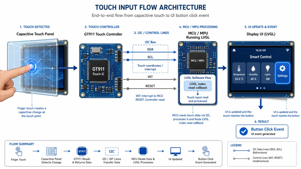
GT911 communicates with the host over I2C and exposes touch status, coordinate data and configuration registers. The interface is simple on paper, but several details matter in real hardware. The controller uses VDD, GND, SCL, SDA, INT and RESET pins. Its I2C interface supports up to 400 kbit/s, but reliable operation above 200 kbit/s depends heavily on pull-up resistance, bus capacitance and signal edge quality. In short cable runs on a four-layer PCB, 400 kHz often works. On long FPC cables, breadboards or noisy prototypes, slowing the bus to 100 kHz is often the fastest diagnostic step.
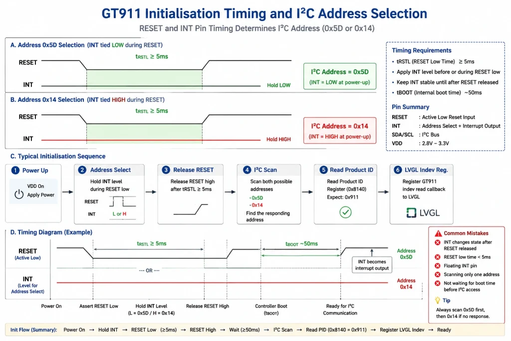
The most important GT911 detail for debugging is address selection. GT911 supports two 7-bit I2C addresses: 0x5D and 0x14. The 8-bit write/read forms are 0xBA/0xBB and 0x28/0x29. The selected address depends on the timing relationship between RESET and INT during power-on or reset. If the firmware assumes 0x5D but the board sequence selects 0x14, every higher-level LVGL check will fail.
In a production industrial touchscreen monitor, these details are hidden inside the touch firmware and USB/I2C bridge. In a custom LVGL project, the engineer owns them. The rule is simple: before registering the LVGL input device, confirm that the host can read a valid GT911 product ID or at least acknowledge the expected I2C address.
Failure Mode 1: GT911 Initialization Failed
The message ‘gt911 initialization failed’ usually means the driver could not talk to the controller during startup. The common causes are wrong I2C address, missing reset sequence, swapped SDA/SCL pins, absent pull-ups, power sequencing problems, a shared LCD reset pin, or a touch panel FPC that is not fully seated.
A disciplined startup test begins outside LVGL. Run an I2C scanner after power-on. If neither 0x5D nor 0x14 appears, check power rails and pin assignment first. If one address appears intermittently, reduce I2C speed to 100 kHz, add a delay after reset, and verify that RESET is not being toggled later by the display driver. Many boards share a reset line between the LCD panel and the touch controller; when the display driver resets the panel after the GT911 driver has already selected its address, the touch chip may silently return to another state.
A robust driver should try both addresses and should not assume the address permanently until it has read a valid ID or coordinate-status register. On ESP32, check that the chosen GPIOs are not strapping pins with unexpected boot behavior. On STM32, confirm that the I2C peripheral is enabled before touch initialization and that the pin alternate functions match the board schematic.
Failure Mode 2: Touch Controller Found, But No Touch Is Reported
The next common case is more confusing: the GT911 responds to I2C, but LVGL never receives a press. This usually means that low-level communication works, while the coordinate-reading path or LVGL read callback is wrong.
GT911 coordinate reading is usually based on the status register at 0x814E. The host checks whether the buffer is ready, reads touch point data, then clears the status so the controller can report the next event. If the driver reads coordinates but never clears the ready flag, later touches can become stale or disappear. If the driver polls too slowly, quick taps may be missed. If the driver relies on INT but the interrupt pin is configured with the wrong edge or pull mode, the firmware may never enter the read path.
In LVGL, the input device must be registered as a pointer-type device and the read callback must return both coordinates and state. A very common bug is reporting x and y but leaving the state as RELEASED, or reporting PRESSED once and never reporting RELEASED. LVGL is not reading the GT911 directly; it trusts the callback. If the callback is wrong, the GUI will be wrong even when the oscilloscope shows a perfect I2C transaction.
Failure Mode 3: Coordinates Are Mirrored, Rotated or Scaled Wrong
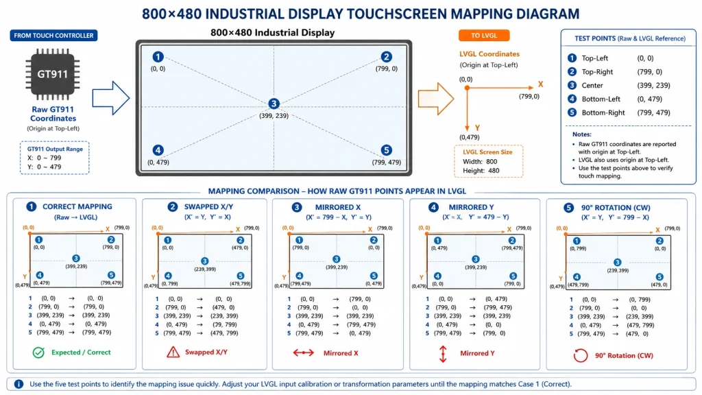
Wrong coordinates are usually not a GT911 hardware failure. They are usually a mapping failure between the touch sensor coordinate system and the display coordinate system. The touch panel may be mounted in landscape while the LCD is driven in portrait. The LVGL display rotation may be set to 90 degrees while the GT911 configuration still reports the native sensor orientation. The display resolution may be 800 x 480, while the GT911 maximum coordinate range is configured as 480 x 800.
Debug this with a simple five-point test: top-left, top-right, bottom-left, bottom-right and center. Print raw GT911 coordinates before LVGL mapping. If x increases in the wrong direction, invert x. If y increases in the wrong direction, invert y. If x and y are swapped, rotate the mapping. If coordinates reach only half the display width, the configured maximum resolution is wrong.
Avoid guessing. A small debug overlay is better than ten firmware rebuilds. Draw a crosshair at the LVGL coordinates returned by the read callback and log the raw values at the same time. Once the physical coordinate transform is correct, keep it in a board-specific layer rather than scattering rotation fixes across application code.
Failure Mode 4: False Double-Clicks, Ghost Taps and Unstable Presses
False double-clicks are usually caused by instability in the press/release state, not by LVGL itself. Capacitive touch is sensitive to grounding, noise, water film, thick cover glass, long cables, poor shielding, charger noise and mechanical pressure near the bezel. If the GT911 reports a rapid sequence of press-release-press at the same location, LVGL may interpret it as a double click.
First, separate software bounce from electrical noise. Log raw status, touch count and coordinates at 5-10 ms intervals. If the raw GT911 data is stable but LVGL double-clicks, tune the input handling, gesture thresholds or application-level click logic. If the raw data itself flickers, inspect grounding and power. A capacitive touch panel needs a clean reference ground. Floating metal enclosures, USB-powered prototypes and long jumper wires are frequent sources of ghost touches.
For industrial HMI displays, the cover glass stack also matters. Optical bonding, cover glass thickness, ink border design, AG/AR coating and water-rejection tuning can all influence touch performance. This is why production products should not be validated only on a bare development panel. Test with the final cover glass, final bezel, final power supply and final enclosure.
GT911 + LVGL Troubleshooting Matrix
The following matrix condenses the most common LVGL touch issues into symptoms, likely causes and first tests. Use it in order: electrical checks first, I2C checks second, GT911 register checks third, and LVGL mapping last.
LVGL Read Callback: The Small Function That Decides Everything
LVGL input integration is deliberately simple. The display driver draws pixels; the input driver periodically reports the current pointer state. For touchpads and mice, LVGL expects an input device of pointer type, a read callback, x/y coordinates and a pressed or released state. This simplicity is useful, but it also hides many mistakes.
A safe LVGL touch callback should do five things. First, read the latest GT911 touch status. Second, verify that the touch count is valid. Third, read the first touch point or selected point. Fourth, apply board-specific coordinate mapping. Fifth, report PRESSED or RELEASED consistently. Do not allocate memory inside the callback. Do not block for long I2C retries. Do not mix gesture logic into the low-level driver.
For multi-touch projects, keep expectations realistic. Basic industrial HMI applications usually need one pointer. If the UI requires pinch, zoom or multiple simultaneous contacts, confirm whether the LVGL version, driver architecture and application widgets are designed for it. Many ‘multi-touch’ hardware panels are integrated as a single pointer in the first product release because it is more reliable for buttons, sliders and process screens.
Hardware Checklist for Industrial GT911 Designs
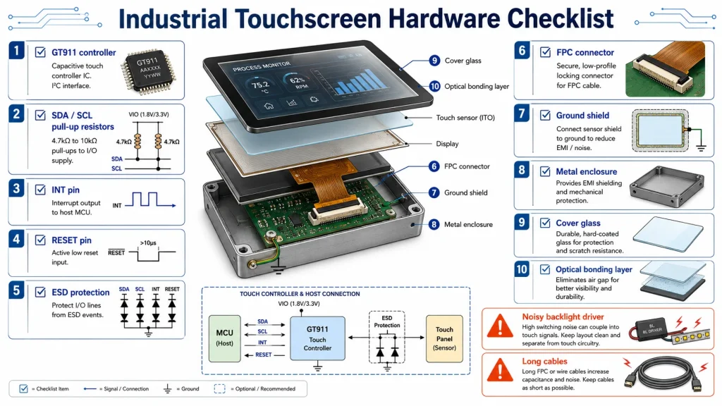
A GT911 touch panel may work on the bench and fail in the field if the hardware environment changes. Industrial products should verify I2C pull-up values, cable length, FPC locking, ground continuity, ESD protection, reset control, INT routing, shield connection and power sequencing. A clean schematic is not enough; the final layout matters. Keep SDA and SCL away from backlight switching nodes, high-current LED traces and noisy DC/DC converters. Add test pads for SCL, SDA, INT and RESET so field failures can be diagnosed without removing the LCD.
The enclosure is part of the capacitive touch system. Thick cover glass, black ink border, metal bezels and adhesive thickness can change sensitivity. If the panel is intended for wet hands, gloves or outdoor kiosks, request touch firmware tuning from the module supplier rather than relying on a phone-style default configuration.
For commercial display projects, using a complete industrial touchscreen monitor can reduce integration risk. Kadi Display, for example, lists industrial monitors with capacitive touch, optional AG/AR/AF surface treatments, wide-temperature operation and customizable bonding, cables, mounting and housing. Those are not cosmetic options; they affect whether touch remains stable after the product is assembled.
Field Debug Workflow: From Dead Touch to Stable HMI
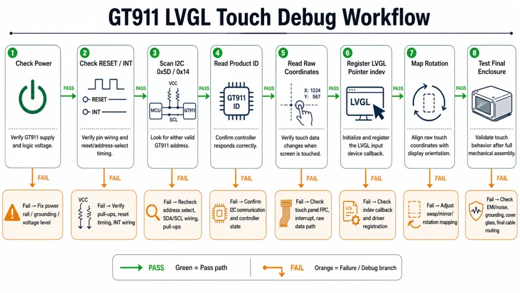
A practical debug flow looks like this. First, power the board and confirm the GT911 power rail with a meter. Second, check RESET and INT with a logic analyzer during boot. Third, scan I2C for both 0x5D and 0x14. Fourth, read the product ID or a known status register. Fifth, read raw touch points outside LVGL. Sixth, register the LVGL pointer input device only after raw touch is stable. Seventh, map coordinates and run the five-point test. Eighth, test for false double-clicks with the final cover glass and power supply.
This order matters because it prevents the most common debugging trap: changing LVGL application code when the controller has never initialized. In most real projects, the problem is not one dramatic bug. It is a mismatch between the board schematic, touch controller timing, driver assumptions and display rotation. Once those layers are separated, GT911 becomes a predictable part rather than a mysterious one.
Summary: Fix the Stack, Not Just the Symptom
When a GT911 touch panel fails in an LVGL project, the symptom is usually simple: no touch, wrong touch or unstable touch. The cause is rarely simple. It may be an I2C address selected at reset, an interrupt pin left in the wrong mode, a stale coordinate buffer, a swapped axis, or electrical noise introduced by the final enclosure.
The strongest engineering habit is to debug from the bottom up. Prove power. Prove reset. Prove I2C. Prove GT911 registers. Prove raw coordinates. Then connect LVGL. For industrial HMI projects, also test the final mechanical stack: cover glass, bonding, bezel, grounding, cable and power supply.
GT911 and LVGL can make a reliable embedded GUI platform for kiosks, medical terminals, vehicle displays, smart appliances, factory HMIs and custom industrial touchscreen monitors. The difference between a fragile prototype and a production-ready touch display is not a single library version. It is a controlled integration process.
Source Notes
GT911 Programming Guide: GT911 communicates through VDD, GND, SCL, SDA, INT and RESET; supports two 7-bit I2C addresses, 0x5D and 0x14; address selection depends on RESET/INT timing; coordinate reading is based on status and coordinate registers.
LVGL Input Device Documentation: LVGL pointer input devices require an input driver structure, pointer type, read callback, coordinates and pressed/released state reporting.
Kadi Display Touchscreen Resources: Kadi Display pages discuss resistive and capacitive touch technologies, industrial touch monitor selection, optional AG/AR/AF treatment, wide-temperature operation, optical bonding and embedded display integration.
Engineering Note: All register and timing values should be checked against the specific GT911 module, touch firmware, board schematic and driver version used in the final product.
Disclaimer
This article is an engineering guide for troubleshooting and content marketing purposes. GT911 register behavior, timing requirements, address selection and LVGL API details may vary by chip revision, touch firmware, board design, LVGL version and driver implementation. Verify all values against the actual module supplier documentation and final hardware. Brand names and product names belong to their respective owners. Avoid copying proprietary datasheet diagrams or confidential vendor text into public marketing pages without permission.
PREVIOUS
How to Choose a Display Manufacturer for Industrial and Medical Equipment Projects
NEXT
Custom Industrial Display vs Off-the-Shelf Display: Which Is Better for B2B Projects?
Leave A Comment

Latest Blog & News
- Industrial LCD EOL: What Happens from Pre-Announcement to Replacement Mass Production?
- Electronic Component Obsolescence Management for Industrial Displays: An OEM Guide
- How to Develop a Production Ready Custom Display Assembly TFT Module Touch Cover Glass FPC Bonding and Mounting
- 15 Pin vs 22 Pin Raspberry Pi DSI Connectors Cable Pinout and Compatibility
- Native MIPI DSI vs LVDS or HDMI Bridge: An OEM Display Architecture Decision Guide

