




Home
-
Blog & News
-
LCD Pressure Damage: Why Industrial Touchscreens Develop Spots After Installation
LCD Pressure Damage: Why Industrial Touchscreens Develop Spots After Installation
2026-07-14
13:32
LCD Pressure Damage: Why Industrial Touchscreens Develop Spots After Installation
How enclosure squeezing, front bezel compression, over-torqued screws, bonding stress, and shipping shock disrupt liquid crystal alignment and light transmission — creating fixed spots and Mura defects that look like manufacturing faults but trace back to mechanical assembly
By Kadi Display Technical Team | www.kadidisplay.com
The Spot That Wasn’t There at the Factory
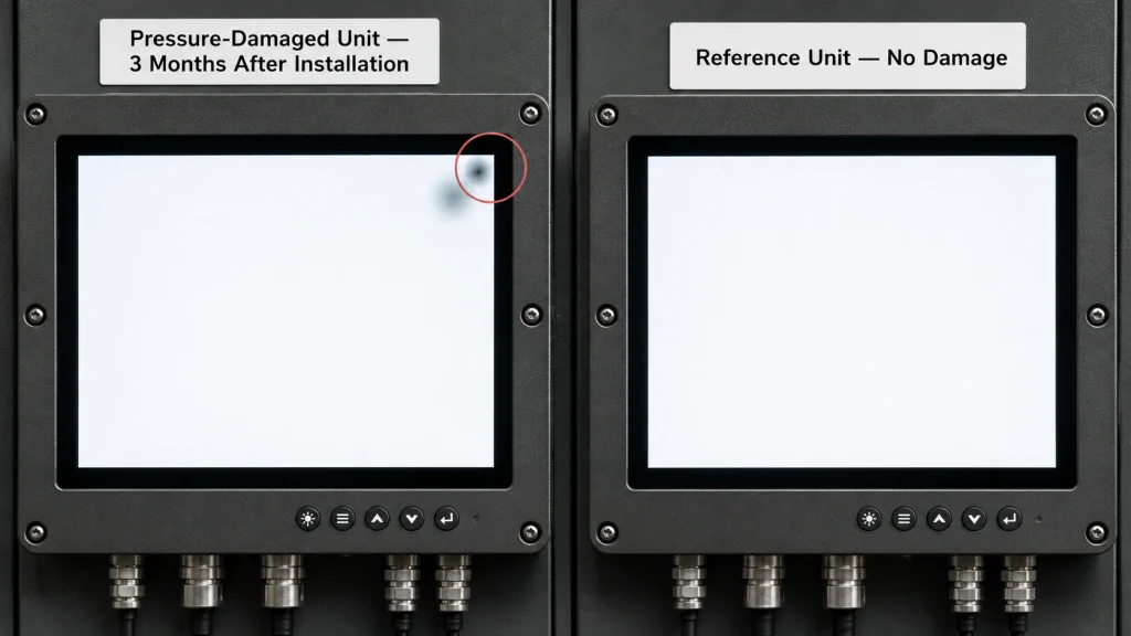
A new industrial touchscreen passes incoming inspection clean. Weeks or months after installation in its final enclosure, a fixed dark or light spot appears on the panel — sometimes a faint cloudy patch, sometimes a sharply defined mark in the exact shape of a mounting boss or screw head. The display still functions. Touch response is normal. But the spot doesn’t move, doesn’t fade, and doesn’t respond to any software fix, because it isn’t a software problem. It’s a mechanical one, and it happened after the unit left the factory.
This failure pattern — visually identical in many cases to a manufacturing defect, but actually caused by mechanical stress introduced during installation, transport, or enclosure assembly — is one of the most frequently misdiagnosed issues in industrial display deployment. Procurement teams return units to the display supplier as defective. Suppliers test the returned unit, find no electrical fault, and the conversation stalls because both sides are looking at the symptom rather than the mechanical event that caused it.
This guide explains the physics of LCD pressure damage, walks through the five mechanical causes most responsible for post-installation spots — structural enclosure squeezing, front bezel over-compression, over-torqued mounting screws, optical bonding stress, and transportation shock — and provides the design rules, torque specifications, and inspection practices that prevent this category of failure from reaching the field in the first place.
The Physics of Pressure-Induced Mura — Why a Squeeze Becomes a Permanent Spot
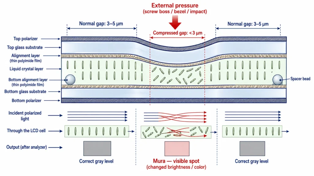
An LCD panel is fundamentally a precision optical sandwich: two glass substrates separated by a liquid crystal layer held at an extremely tight and uniform gap — typically 3 to 5 micrometers, controlled by spacer beads or photo-spacers distributed across the active area. The entire optical performance of the panel — contrast, color accuracy, light transmission — depends on that gap remaining uniform to within a fraction of a micrometer across the full viewing surface.
When a localized mechanical force is applied to the front of the panel — from a bezel pressing too hard, an enclosure wall squeezing the edges, or a screw boss pushing up from behind — the glass substrates flex locally. Even a deflection too small to see with the naked eye is enough to compress the cell gap in that specific area. A cell gap compressed by as little as 0.3 to 0.5 micrometers measurably changes the liquid crystal’s retardation value — the parameter that determines how the panel manipulates polarized light to produce each grey level. The visual result is a spot or smear with different brightness, different color tint, or different contrast than the surrounding unstressed area — the defect pattern known in the display industry as Mura, a term referring to non-uniform brightness or color across an otherwise uniform image.
Two outcomes are possible depending on the magnitude and duration of the force. If the stress is below the LC fluid’s elastic limit and is removed within a short period, the liquid crystal alignment layer can recover, and the spot fades over hours to days. If the stress exceeds the elastic limit — common with sustained pressure from an over-torqued screw or a permanently compressed bezel gasket — the alignment layer suffers localized mechanical damage that does not self-correct. This is why pressure spots from a one-time shipping impact sometimes fade, while spots from a continuously over-tightened screw do not: one is a transient mechanical insult, the other is a sustained one.
Five Mechanical Causes of Pressure Damage — and How Each Leaves a Distinct Signature
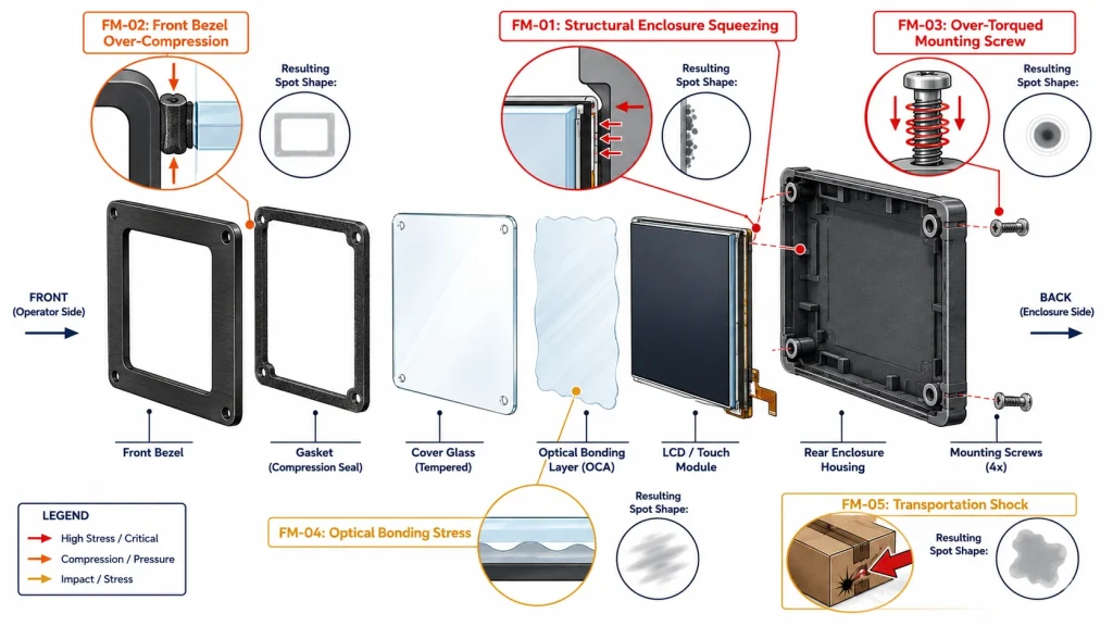
Pressure damage is not a single failure mode — it has at least five distinct mechanical origins, each with a characteristic spot location, shape, and timing that helps trace the defect back to its root cause during a field failure investigation.
FM-01 · Structural Enclosure Squeezing
Mechanism: When an enclosure is designed with insufficient internal clearance, the housing walls or internal ribs make direct contact with the display module’s edges or rear surface. As the enclosure is assembled and fasteners are tightened, the housing can flex or compress against the display, applying a continuous edge-load or point-load that the display was never designed to absorb. This is especially common in compact panel-mount HMI enclosures where space is tight and the display module is treated as a rigid component rather than one with finite mechanical tolerance.
Field Evidence: Spots from enclosure squeezing typically appear along the panel edges or at specific points where internal ribs or standoffs contact the rear of the display — often in a line or cluster pattern that mirrors the enclosure’s internal rib layout. The defect is frequently present from very shortly after final assembly, sometimes visible during final functional test if the test occurs after full enclosure closure rather than before.
Prevention: Specify a minimum clearance envelope around the display module — typically 0.5–1.0 mm on all sides plus a defined rear clearance behind the active area — as a mechanical design requirement, not an assumption. Verify clearance using the actual display module’s mechanical drawing, not just the advertised active area dimensions, since bezel and FPC tail positions vary between suppliers even at the same nominal screen size.
FM-02 · Front Bezel Over-Compression
Mechanism: The front bezel — whether a metal frame, plastic trim ring, or the enclosure’s front panel cutout — is frequently designed with a foam or rubber gasket between the bezel and the display’s front glass to provide sealing and vibration damping. If this gasket is over-compressed during assembly, either from incorrect gasket thickness selection or from fasteners drawn down beyond the gasket’s rated compression range, the bezel transmits a sustained, distributed pressure directly onto the display’s front surface.
Field Evidence: Bezel-related pressure damage typically appears as a spot or band that follows the bezel’s contact perimeter — often visible as a faint rectangular or frame-shaped shadow near the edge of the active area, rather than an isolated circular spot. It commonly develops gradually over weeks as the gasket material continues to compress under sustained load.
Prevention: Specify gasket compression within the manufacturer’s rated range — typically 20–30% of original thickness for closed-cell foam gaskets used in display sealing applications; compression beyond 40% accelerates both gasket degradation and the risk of transmitting damaging force to the glass. Confirm bezel fastener torque is controlled rather than tightened to a “feels right” standard during assembly.
FM-03 · Over-Torqued Mounting Screws
Mechanism: Display modules are typically secured using mounting holes at the corners or edges of the module’s metal frame or PCB, with a small but finite clamping force intended to hold the module against vibration without transmitting structural load into the LCD cell itself. When a screw is tightened beyond its specified torque, the clamping force at that point can exceed what the module’s frame is designed to distribute safely, transmitting a concentrated point load through the frame and into the glass directly above or near the screw location.
Field Evidence: Over-torque damage is among the most visually distinctive pressure failure modes: a sharply localized spot, often nearly circular or matching the screw head or boss shape, positioned directly at or adjacent to a mounting hole. Because the stress is sustained continuously by the screw’s clamping force, these spots do not fade over time and frequently worsen slightly if the unit experiences additional vibration or thermal cycling.
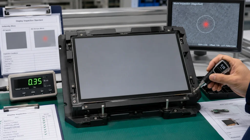
Prevention: Specify and enforce exact torque values for every mounting screw using a calibrated torque screwdriver rather than a standard driver tightened by feel. Train assembly technicians explicitly on this requirement, since “snug” by hand-feel calibration varies significantly between individual operators and frequently exceeds rated torque on small M2–M3 fasteners.
FM-04 · Optical Bonding and Adhesive Lamination Stress
Mechanism: Optical bonding — laminating the cover glass directly to the LCD or touch panel using an optically clear adhesive — eliminates the air gap that would otherwise allow the display to flex independently of the cover glass. This significantly improves optical performance and durability, but it also means any stress applied to the cover glass after bonding transmits much more directly into the LCD cell than it would through an air-gapped, unbonded touch stack.
Field Evidence: Bonding-stress spots can appear anywhere across the active area depending on where uneven adhesive thickness or curing stress occurred during lamination, but they are frequently distinguishable from mounting-related damage by their soft, diffuse edge and tendency to follow a curved or streak pattern rather than a sharp geometric shape.
Prevention: Specify a qualified optical bonding process with documented adhesive thickness uniformity and a controlled cure profile rather than treating bonding as a generic value-added step. Confirm with the display supplier what bonding process — wet OCA, dry OCA, or liquid OCR — is used and request evidence of uniformity inspection.
FM-05 · Transportation and Handling Shock
Mechanism: Shipping introduces mechanical shock and vibration profiles that differ substantially from anything the display experiences during installation or operation. A dropped pallet, a forklift impact, an under-protected corner of a shipping carton, or a sustained vibration profile from poorly cushioned truck or rail transport can apply momentary but high-magnitude force to the display’s front surface or edges.
Field Evidence: Shock-induced spots are often irregular in shape and location, since the contact point during an impact event is rarely centered on the panel and can occur anywhere a packaging gap allowed movement. A useful diagnostic clue: shock damage frequently coincides with other visible signs of impact — a dented enclosure corner, a cracked cover glass edge, or scuff marks on packaging.
Prevention: Maintain original display packaging through final installation wherever the assembly process allows. For finished-product shipping, specify cushioning validated to ASTM D4169 or ISTA transportation test profiles appropriate to the shipping mode and route, with particular attention to corner and edge protection.
Torque, Gasket, and Packaging Specifications That Prevent the Most Common Failures
Most pressure damage traces back to a process step performed without a documented, enforced specification — a screw tightened by feel, a gasket compressed without a defined target, or a shipment packed without a validated cushioning standard. The following reference values give engineering and quality teams a concrete starting point for specification development.
Mounting Screw Torque Reference
⚠ Torque Values Are a Starting Reference, Not a Universal Standard
Actual torque specifications must come from the display module manufacturer’s mechanical drawing or assembly instructions for the specific module — frame material, mounting boss design, and module size all affect the safe torque range. The values above are representative starting points for engineering review, not a substitute for supplier-specified torque on a given product.
Gasket Compression and Bezel Design
Shipping and Packaging Validation
- ASTM D4169 — Standard Practice for Performance Testing of Shipping Containers and Systems. Defines distribution cycle testing appropriate to the assigned distribution category for the shipping route and handling method.
- ISTA test procedures — Widely used alternative or complementary standards for validating packaging performance against drop, vibration, and compression hazards specific to small parcel, LTL, or full truckload shipping.
- Drop height reference: a common qualification target for boxed display modules under 5 kg is corner and flat drops from 760 mm, though actual required height should be set based on the specific carrier and handling chain.
Detecting Pressure Damage Before It Reaches the Field
Because pressure damage frequently develops gradually — particularly bezel compression-set and over-torque stress — a single incoming inspection at receiving may pass a unit that develops a visible spot weeks later. A more effective inspection strategy combines immediate post-assembly checks with a delayed verification step.
The fifth inspection point — AOI during manufacturing — addresses a different but related question: confirming the panel did not already carry latent bonding stress before it reached the customer’s assembly line. Suppliers running 100% automated optical inspection during the bonding and FOG process provide assurance that incoming panels start from a Mura-free baseline, which makes any spot appearing after receipt much easier to attribute correctly to a downstream mechanical cause rather than disputing whether it existed at shipment.
Design Rules for Procurement and Mechanical Engineering Teams
Preventing pressure damage requires coordination between mechanical design, assembly process control, and supplier qualification — three functions that do not always communicate directly during a product development cycle. The following design rules consolidate the guidance from this article into items that belong explicitly in a mechanical design review or supplier qualification checklist.
Sourcing Display Modules and Bonding Processes That Reduce Pressure Damage Risk
The mechanical design rules in this guide reduce risk regardless of which display supplier is used, but the baseline difficulty of avoiding pressure damage varies with how the display module itself is engineered and how its bonding process is controlled. Modules with a well-documented mechanical drawing, a confirmed bonding process with uniformity inspection, and clear mounting guidance start the integration process with substantially less risk than a module where these details must be inferred or requested repeatedly during a project.
Kadi Display’s guide on optical bonding for industrial displays explains the wet versus dry OCA/OCR bonding process distinction directly relevant to this discussion of bonding-induced stress, while their companion article on combining a display with a touch panel through optical bonding specifically addresses how adhesive material tension during the bonding process can cause mechanical distortions that become visible in dark UI content — the same Mura mechanism described in this guide.
For broader mechanical fit and mounting structure guidance during display module selection, Kadi Display’s industrial TFT LCD display module selection guide recommends confirming connector position, FPC direction, and mounting structure before sample approval. Their comparison of custom versus off-the-shelf industrial displays similarly notes that mechanical fit is a common failure point.
Product Reference & Engineering Support
For industrial TFT-LCD display modules with documented mechanical drawings, controlled optical bonding processes, and AOI-inspected manufacturing for uniform, Mura-free panels, contact Kadi Display at Sales@sz-kadi.com. OEM and ODM services available including custom mounting structure and bonding process consultation. Browse industrial display module options →
Summary — Treating the Display as a Precision Component, Not a Rigid One
LCD pressure damage is preventable almost entirely through process discipline rather than expensive design changes: correct clearance in the enclosure drawing, a specified and enforced gasket compression target, calibrated torque on every mounting screw, a qualified bonding process with uniformity verification, and packaging validated against a real transportation hazard profile. None of these requires premium component pricing — they require treating the display module as the precision optical component it actually is, rather than a rigid mechanical part that tolerates whatever clamping force feels appropriate during assembly.
For procurement and engineering teams investigating an unexplained spot on a returned or field-reported unit, the diagnostic path in this guide — matching spot location, shape, and timing against the five mechanical failure signatures — frequently resolves the root-cause question faster than an extended back-and-forth with the display supplier over whether the defect was present at shipment.
Disclaimer: Torque values, compression percentages, and testing standard references in this guide are representative engineering starting points for design review and must be verified against the specific display module manufacturer’s mechanical specifications and applicable industry standards for your product. ASTM and ISTA are registered standards bodies; this article references their general testing categories for educational purposes and does not reproduce their proprietary test procedures. All brand and product names are the property of their respective owners. No affiliation with ASTM International or ISTA is implied.
PREVIOUS
GT911 Touch Coordinate Offset in LVGL: Causes and Calibration Methods
NEXT
Designing Industrial LCD HMIs for 10-Year Operation Without Image Retention Problems
Leave A Comment

Latest Blog & News
- Industrial LCD EOL: What Happens from Pre-Announcement to Replacement Mass Production?
- Electronic Component Obsolescence Management for Industrial Displays: An OEM Guide
- How to Develop a Production Ready Custom Display Assembly TFT Module Touch Cover Glass FPC Bonding and Mounting
- 15 Pin vs 22 Pin Raspberry Pi DSI Connectors Cable Pinout and Compatibility
- Native MIPI DSI vs LVDS or HDMI Bridge: An OEM Display Architecture Decision Guide

