




Home
-
Blog & News
-
ZIF Connectors for Capacitive Touch Panels: Avoiding GT911 Touch Failures from FPC Contact Problems
ZIF Connectors for Capacitive Touch Panels: Avoiding GT911 Touch Failures from FPC Contact Problems
2026-07-04
10:57
ZIF Connectors for Capacitive Touch Panels: Avoiding GT911 Touch Failures from FPC Contact Problems
How poor FPC seating, mismatched connector pitch, CTE-driven micro-separation, and contamination on ZIF contacts cause GT911 I²C detection failures — and what engineers can do at design time, assembly time, and bring-up to prevent them
By Kadi Display Technical Team | www.kadidisplay.com
The Connector Nobody Blames — Until Everything Else Checks Out
There’s a well-worn pattern in GT911 bring-up failures. The engineer runs through the obvious list: power supply voltage, I²C pull-up resistors, RST and INT pin sequencing, firmware address configuration. Everything checks out. The oscilloscope shows clean SDA and SCL signals. The MCU drives RST correctly. The I²C scan still returns nothing. The GT911 is not found at 0x5D or 0x14.
At this point, most engineers go back to software. They restructure the reset sequence, try different SDK versions, swap the I²C bus number. Hours pass. Occasionally someone physically removes the display module from the development fixture and reseats it — and suddenly the GT911 appears on the I²C scan as if nothing happened. That moment of accidental discovery is the connector telling you what it’s been trying to say all along.
The FPC (flat printed circuit) cable and its ZIF (zero insertion force) connector are the physical link between the GT911 touch controller on the display module’s flex PCB and the host board’s I²C lines. This link is mechanically fragile, geometrically intolerant of misalignment, vulnerable to corrosion and contamination, and subject to progressive fatigue from thermal cycling and vibration. In development, it gets handled dozens of times. In production, a single assembly step determines whether this connection survives years of factory floor operation. Getting it right is not accidental — it requires specific knowledge about how ZIF connectors work, how FPC cables fail, and how to verify the connection before it fails in the field.
How ZIF Connectors Work — and Where the Physics Creates Failure Risk
A ZIF (zero insertion force) connector for FPC cables is built around one key mechanical principle: the cable is inserted without any lateral clamping force, then a locking actuator is flipped down or slid forward to engage the conductor pads on the cable against the connector’s spring contacts. The ‘zero insertion force’ name refers to the insertion phase only — the clamping is added by the actuator closure. This design enables repeated insertion without wearing the cable or connector, which is why it’s ideal for flexible cables used in display assemblies.
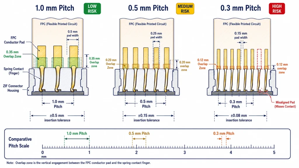
The ZIF contact mechanism depends on a precise overlap between the cable’s conductor pads and the connector’s spring fingers. This overlap is typically 0.3–0.5 mm in small-pitch connectors. For the GT911’s I²C lines (SDA, SCL, INT, RST, VDD, GND — often on a 6-pin or 10-pin FPC), each conductor pad is itself only 0.3–0.5 mm wide at 0.5 mm pitch, or narrower at 0.3 mm pitch connectors used in compact modules. A cable that’s inserted even 0.2 mm short of full seating may leave one or two conductors — potentially the SDA or SCL line — outside the contact overlap zone. The circuit is incomplete. The I²C bus sees no device.
Connector Pitch and Its Effect on Contact Sensitivity
FPC connectors for capacitive touch panels come in two dominant pitch standards. Understanding which standard a given module uses, and the tolerance requirements each imposes, is the foundation of avoiding connector-related failures.
The 0.5 mm pitch connector is the most common in the GT911 touch module ecosystem. At this pitch, the contact pad is only 0.25 mm wide. A misalignment of 0.2 mm — roughly the diameter of two human hairs side by side — is enough to move a critical conductor out of the contact zone. This level of precision is achievable in automated assembly with a production fixture. It is frequently exceeded in manual bench assembly, especially when the engineer is inserting and removing the cable repeatedly during bring-up.
Six Failure Modes That Look Like GT911 Firmware Bugs
Each of the following failure modes produces an I²C detection failure — the GT911 is not found at any known address, or is found intermittently — that is indistinguishable from a firmware or hardware reset sequence problem without physically examining the connector. They are presented in order of frequency.
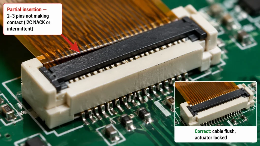
FM-01 Partial FPC Insertion — The Most Common First-Day Failure
Symptom: GT911 not found on I²C scan. Reseating the cable fixes it immediately. Problem recurs when cable is disturbed. Firmware and power supply checks show no issues.
Root Cause: The FPC cable is not fully inserted to the stop position in the ZIF connector. Typically 0.5–2 mm of cable is left outside the connector body. At 0.5 mm pitch, this moves 1–4 conductor pads out of the contact zone — often including SDA or SCL, breaking the I²C circuit entirely.
Fix: Open the ZIF actuator (flip it to the ‘open’ position). Remove the cable fully. Inspect the insertion depth mark on the cable — most FPC cables have a line or chamfer indicating the correct insertion point. Reinsert until the mark aligns with the connector body edge. Close the actuator. Verify by gently pulling the cable horizontally — a correctly seated cable resists movement. Run the product ID check (I²C read of 0x8140) to confirm.
FM-02 ZIF Actuator Not Fully Locked
Symptom: GT911 found on I²C scan initially, then disappears after the first vibration or temperature change. Contact resistance increases from < 30 mΩ to > 500 mΩ. Error appears correlated with mechanical events or thermal cycling.
Root Cause: The ZIF actuator was closed but not fully engaged. Many ZIF actuators have a two-stage action: a partial close that feels complete but leaves the spring contacts at reduced clamping force, and a full-close that applies the rated contact pressure. An under-actuated connector passes initial continuity checks but loses contact under vibration or FPC dimensional change from temperature.
Fix: With the PCB powered off, press the actuator firmly with a fingernail or flat tool until a distinct click or positional stop is felt. Check the actuator top surface with a loupe — a correctly locked actuator sits flush with the connector housing with no visible gap at either end. For production, specify the actuator closing force in the assembly procedure and include a go/no-go visual check under magnification.
FM-03 CTE Mismatch — Thermal Cycling Loosens the Contact
Symptom: GT911 touch works reliably at room temperature. I²C errors appear after the system reaches steady-state operating temperature (typically +50°C or above), or during cold starts below 0°C. Contact resistance measurement shows values that increase with temperature cycling count.
Root Cause: Thermal expansion mismatch between the polyimide FPC (CTE ≈ 20 ppm/°C) and the FR4 PCB hosting the ZIF connector (CTE ≈ 17 ppm/°C). Over 50 thermal cycles from −20°C to +70°C, the cumulative relative movement at the connector exit point is approximately 0.03 mm per centimeter of cable length — enough to progressively work the cable backward out of the contact zone by a fraction of a millimeter, crossing the contact margin threshold.
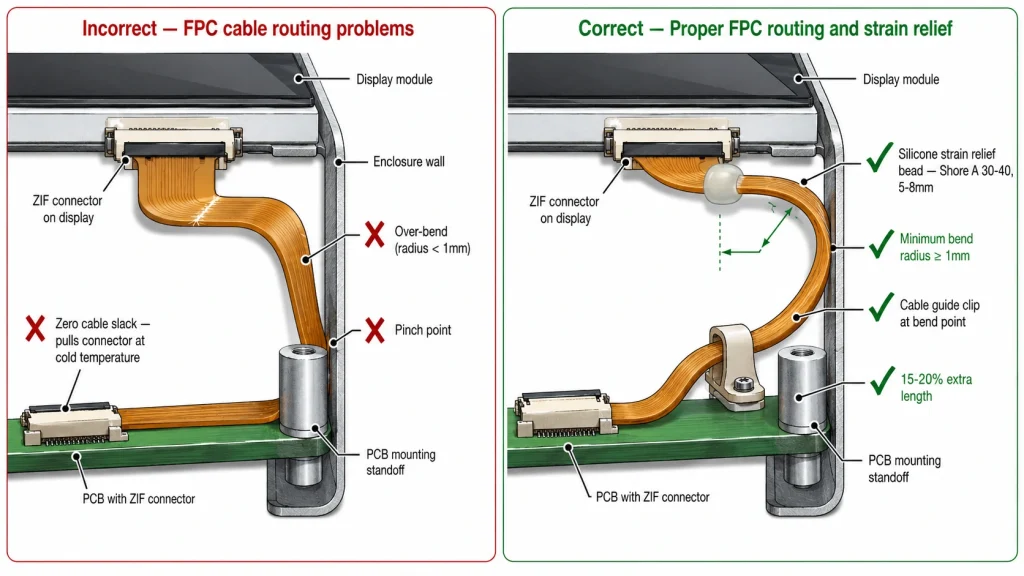
Fix: Apply a silicone strain relief bead (Shore A 30–40) at the point where the FPC exits the ZIF connector housing. The bead distributes the thermal expansion stress over a bend radius rather than concentrating it at the connector edge. Minimum bead length: 5 mm. Verify by running 50 thermal cycles (−20°C to +70°C, 30 min per extreme) and measuring SDA/SCL continuity at each extreme. Target: < 1 Ω at all measured points throughout the test.
FM-04 Contamination on FPC Conductor Pads
Symptom: GT911 not found on first bring-up after display module arrives from supplier. Actuator appears correctly seated. No improvement from reseating the cable in the same orientation. Cleaning the contact area and reseating resolves the problem.
Root Cause: Oxide layer, soldering flux residue, or handling contamination on the FPC conductor pads increases contact resistance beyond the threshold for valid I²C signal levels. Gold-plated pads are resistant to oxidation but not immune; tin-plated or silver-plated pads oxidize within months in humid or sulfur-containing environments. Even clean finger contact leaves organic contamination from skin oils that can increase pad resistance by 10–100×.
Fix: Clean FPC conductor pads using isopropyl alcohol (IPA) ≥ 99.5% purity on a lint-free swab before insertion. Never touch conductor pads with bare fingers after cleaning. For production, store FPC cables in sealed ESD bags with desiccant. If operating in environments with high sulfur content (rubber vulcanization facilities, some food processing environments), specify gold-finished FPC pads and gold-plated ZIF contacts.
FM-05 Wrong FPC Insertion Direction — Contacts Facing Away
Symptom: GT911 not found on I²C scan on a new board or after replacing the FPC cable. Reseating in the same orientation has no effect. All other diagnostics show correct power and firmware behavior.
Root Cause: FPC cables for ZIF connectors come in two types: contacts-up (conductor pads facing upward as inserted) and contacts-down (conductor pads facing downward). Most ZIF connectors are designed for one orientation. Inserting a contacts-up cable into a contacts-down connector places the cable’s insulation layer against the spring contacts — the conductors never make electrical contact regardless of insertion depth or actuator engagement.
Fix: Check the FPC cable markings: cables often have a printed label indicating contact side, or the conductor pads are visible on one face only. Check the ZIF connector datasheet for the required cable insertion direction. If the connector requires contacts-down and the cable is contacts-up, a 180° flip is required — which changes which face of the cable is visible. Note that flipping the cable also changes which signals map to which connector pins, requiring a cable design change unless the FPC is designed symmetrically.
FM-06 FPC Cable Damage from Over-Bending
Symptom: GT911 works initially on first power-up. Contact is lost after routing the cable through the enclosure. Fault appears at a specific bend location visible as a white stress mark or crease on the FPC.
Root Cause: FPC cables have a minimum bend radius — typically 10× the cable thickness for static bending, 20× for dynamic (repeated) bending. A standard 0.1 mm thick FPC has a minimum static bend radius of approximately 1 mm. Bending tighter than this fractures the thin copper conductor traces (typically 18–35 µm thick) inside the polyimide, creating an open circuit that may initially show marginal continuity but fails completely within a few thermal cycles.
Fix: Inspect the cable for any visible creases, white stress marks, or areas of increased stiffness along its routing path. Bend radius at any point must meet the cable manufacturer’s specification. For enclosure routing, use a cable guide or clip to enforce the minimum radius. If the route requires a tight bend, specify a longer cable routed around the constraint rather than through it. Replace any cable showing visible crease damage — fractured copper traces do not self-heal.
Measuring Contact Resistance — The Diagnostic That Ends Guesswork
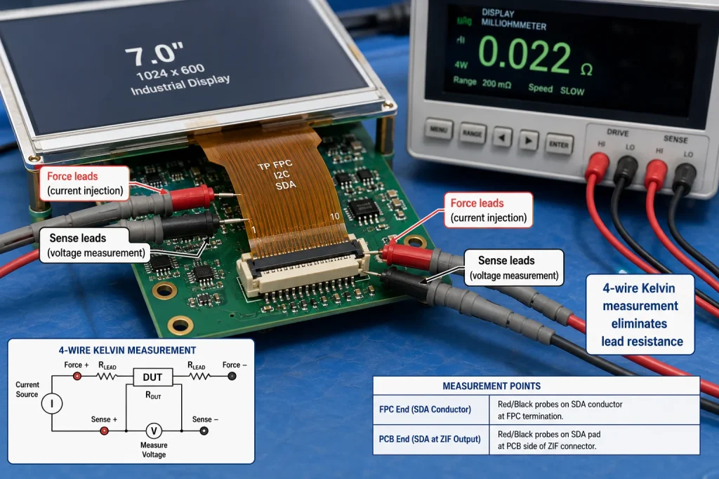
The most efficient way to distinguish a connector failure from an I²C firmware problem is to measure the FPC contact resistance directly. This test takes less than five minutes and eliminates all six connector failure modes described above in a single measurement pass.
Four-Wire Kelvin Measurement Procedure
Standard two-wire resistance measurement at milliohm values is dominated by the measurement leads’ own resistance. For FPC contact resistance, where the target value is < 30 mΩ and failure typically manifests above 100 mΩ, a four-wire (Kelvin) measurement is required. The procedure:
- Step 1: Leave the FPC cable seated in the ZIF connector with the system powered off.
- Step 2: Identify the SDA and SCL conductor pads on the FPC. On most GT911 modules they are pins 2 and 3 of the touch FPC connector — confirm with the module’s FPC pinout document.
- Step 3: Using a milliohmmeter or a 4-wire LCR meter, clip the force leads to each SDA pad end (FPC side and PCB pad side), and the sense leads to the same pads.
- Step 4: Record resistance for SDA, then repeat for SCL, RST, INT, VDD, and GND conductors.
- Step 5: Compare to pass/fail criteria: < 30 mΩ = contact acceptable; 30–100 mΩ = marginal; > 100 mΩ = connector or cable fault confirmed.
If this measurement isn’t available, a simplified version using a standard bench multimeter in continuity/diode mode provides a binary result: a working contact gives a tone or a resistance reading below about 5 Ω; a failed contact gives an open circuit reading. This won’t quantify the margin, but it identifies clear failures.
The I²C Connection Between FPC Failure and GT911 LVGL Behavior
Understanding how a marginal FPC contact produces specific LVGL touch behavior helps engineers correlate field symptoms back to the connector without requiring physical access to the hardware. These patterns appear consistently across GT911 + LVGL deployments where connector reliability is the root cause.
The INT pin FPC contact case (fourth row in the table above) deserves particular attention. If the INT line has marginal contact resistance during the GT911 reset sequence, its level may float to an indeterminate state at the moment RST transitions HIGH — the exact window when the GT911 samples INT to determine its I²C address. A floating INT line that reads HIGH selects address 0x14. Firmware configured for 0x5D finds nothing. This is one of the few failure modes where the FPC connector directly controls the I²C address selection behavior, producing a symptom that looks exactly like an RST sequencing firmware bug.
Design-Time Practices That Prevent Field Failures
The most effective intervention point for ZIF connector reliability is the PCB design and mechanical enclosure design stage, not the debugging stage. These practices eliminate the majority of connector failure modes before the first unit is assembled.
PCB Layout Around the ZIF Connector
- Protect pull-up resistors from mechanical stress: Place the I²C SDA/SCL pull-up resistors within 5 mm of the ZIF connector pads, not at the MCU end of a long trace. This limits the length of trace that can pick up noise from a marginal connector contact and reduces the rise time impact of even slightly increased contact resistance.
- Avoid via-in-pad under the ZIF connector footprint: Vias under or immediately adjacent to ZIF connector pads can create surface topology variations that prevent full FPC pad seating. Maintain a 0.5 mm via-free keepout around the ZIF connector footprint.
- Add a strain relief feature to the PCB design: A mechanical finger or clip molded into the PCB edge or enclosure housing that holds the FPC at the correct cable angle prevents over-bending and limits vibration-induced movement at the connector entry. This is a standard feature in consumer electronics production that is often omitted in prototype industrial designs.
Mechanical Enclosure Design Considerations
- Cable routing guide before enclosure closure: Design a cable routing channel in the enclosure that enforces the minimum bend radius and prevents the cable from being pinched or over-bent during assembly. The routing path should be visible to the assembler before the enclosure is closed.
- Cable length allowance for thermal movement: Leave 15–20% slack in the FPC cable route compared to the measured straight-line distance. Cables routed with zero slack have no accommodation for thermal expansion length changes and may pull backward from the connector under cold temperature contraction.
- Silicone strain relief application as a production step: Include the silicone strain relief bead application as a mandatory assembly step with a written procedure specifying bead length (5–8 mm), position relative to connector exit, and cure time before functional test.
Production Assembly Verification — Catching Failures Before Shipment
At production scale, connector failures that escaped bench bring-up cause field failures that cost far more to resolve than the time invested in production verification. These three verification steps, added to the end-of-line test sequence, catch the dominant connector failure modes before product ships.
📌 The GT911 Product ID Read as a Pass/Fail Test
The fastest single-point production test for FPC connector integrity is a direct I²C read of the GT911 product ID register 0x8140. Expected response: ASCII characters ‘9’, ‘1’, ‘1’, followed by 0x00. This read requires valid contact on at minimum SDA, SCL, VDD, and GND conductors. If any of these four has a contact failure, the read will fail with NACK or return all-zero data. The test takes under 100 ms and can be automated in an ICT fixture with an I²C master adapter. See the GT911 + LVGL integration guide at kadidisplay.com for the complete I²C register read procedure.
Connector Selection Criteria for Industrial Applications
Not all ZIF connectors for a given pitch are equivalent in industrial reliability. Consumer connectors optimized for cost in a smartphone assembly have different specifications from connectors designed for industrial or automotive applications. These are the parameters that determine which category a connector falls into:
Connecting FPC Reliability to the Broader GT911 + LVGL System
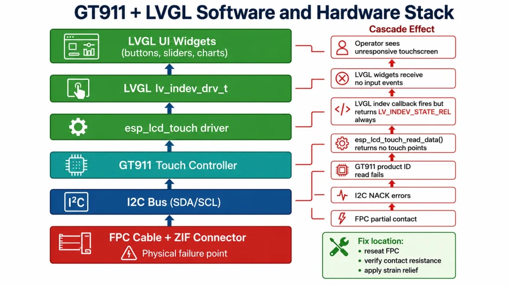
FPC connector reliability sits at the bottom of the GT911 + LVGL software stack but directly determines whether the top of the stack — the LVGL UI widgets, the touch callbacks, the input device driver — functions at all. Engineers working through the GT911 bring-up process on ESP32-S3 or Raspberry Pi platforms sometimes spend significant time ruling out software causes for what is ultimately a physical connection problem that a five-minute measurement would have identified immediately.
The practical integration between connector reliability and software stability works in both directions. A well-seated, strain-relieved FPC connector with gold contacts provides the stable I²C communication that the GT911 driver and LVGL indev callback layer assume. An unstable connector produces intermittent NACK errors that the software layer must handle gracefully — through I²C bus recovery, automatic GT911 reset, and LVGL watchdog restart — but cannot prevent entirely. Designing the software for connector-related intermittency is necessary but not sufficient; the physical connection must be correct first.
For engineers working through the full GT911 + LVGL integration stack, Kadi Display’s technical guide on connecting a GT911 capacitive touch panel to LVGL on ESP32-S3 covers the complete software stack — I²C initialization, reset sequence, LVGL indev registration, and touch coordinate mapping — on the assumption that the FPC connector is correctly seated and the hardware layer is stable. Separately, their guide on choosing an industrial TFT LCD display module addresses connector position, FPC direction, and touch interface selection as part of the broader module procurement decision.
Summary — What the FPC Connector Needs from Hardware Engineers
The ZIF connector for a GT911 capacitive touch FPC is not a passive mechanical component. It is an active part of the I²C circuit that determines whether the touch controller is visible to the system at all. Treating it as an afterthought — inserting the cable without verifying seating depth, skipping strain relief because it ‘seems robust enough,’ selecting a consumer-grade connector for a 7-year industrial product — produces field failures that could have been prevented at the design stage for a few hours of engineering attention.
Product Reference & Technical Support
For industrial TFT-LCD display modules with factory-calibrated GT911 capacitive touch, confirmed FPC pinout documentation, and industrial-grade connector specifications for reliable I²C bring-up on ESP32-S3, Raspberry Pi CM4, and similar embedded platforms, contact Kadi Display at Sales@sz-kadi.com. OEM and ODM services available. Browse industrial TFT touch display modules →
Disclaimer: Resistance values, contact force specifications, and failure mode data in this guide are representative industry figures for educational reference and must be validated against the specific connector, cable, and environment in your design. GT911 is a trademark of Shenzhen Goodix Technology Co., Ltd. All other trademarks are the property of their respective owners. No affiliation with any connector manufacturer is implied. Compliance testing for industrial environments must be conducted by an accredited laboratory.
PREVIOUS
Common MIPI DSI Display Problems: Black Screen, Flicker, No Backlight, and Driver Issues
NEXT
Zero Insertion Force Connectors in Industrial LCD Displays: Why They Matter
Leave A Comment

Latest Blog & News
- Industrial LCD EOL: What Happens from Pre-Announcement to Replacement Mass Production?
- Electronic Component Obsolescence Management for Industrial Displays: An OEM Guide
- How to Develop a Production Ready Custom Display Assembly TFT Module Touch Cover Glass FPC Bonding and Mounting
- 15 Pin vs 22 Pin Raspberry Pi DSI Connectors Cable Pinout and Compatibility
- Native MIPI DSI vs LVDS or HDMI Bridge: An OEM Display Architecture Decision Guide

