




Huis
-
Blog & Nieuws
-
Industrial LCD Failure Modes: Image Retention, Burn-in, Mura, Spot Damage and Backlight Aging
Industrial LCD Failure Modes: Image Retention, Burn-in, Mura, Spot Damage and Backlight Aging
2026-07-07
11:43
Industrial LCD Failure Modes: Image Retention, Burn-in, Mura, Spot Damage and Backlight Aging
A Comprehensive Reliability Reference for Industrial Display Engineers
Door het technische team van Kadi Display | www.kadidisplay.com
Introduction: Why Industrial LCDs Fail Differently Than Consumer Screens
A consumer monitor sitting in an air-conditioned office rarely sees more than a 15°C swing in ambient temperature over its lifetime. An industrial LCD mounted in an outdoor kiosk, a factory HMI panel, or a vehicle dashboard can swing through a 100°C+ range in a single day — baking at 70°C under direct sun in summer afternoons, then dropping below freezing overnight. That thermal stress, combined with continuous operation (often 24/7 for 5–10 years), is why industrial LCD failure modes look fundamentally different from the failures a consumer ever notices on a laptop or TV.
According to reliability data compiled across industrial display deployments, the dominant root causes of field failures fall into five buckets: image retention and burn-in, mura (non-uniform brightness or color patches), localized spot damage, backlight aging and degradation, and polarizer or optical-bonding breakdown under thermal cycling. Together these account for the overwhelming majority of warranty returns reported by panel integrators in industrial automation, transportation, and outdoor signage segments.
This article walks through each failure mode in depth — what causes it, how to recognize it, what the underlying physics or chemistry actually does to the panel, and what design choices reduce the risk. Along the way we’ll reference the engineering specifications that separate a display rated for 5 years of continuous industrial duty from one that will show visible degradation within 18 months.
Image Retention: The Early Warning Sign Engineers Often Ignore
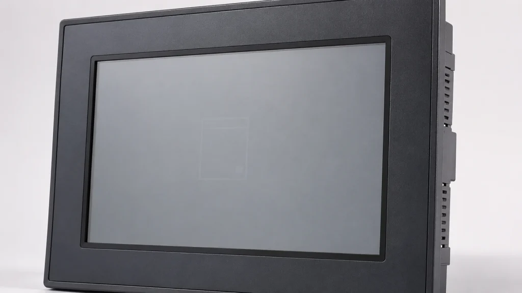
Image retention is the temporary ‘shadow’ of a static image that lingers after the screen content changes. It is the most common early symptom in industrial LCDs because so many industrial applications display the same UI layout — a control panel, a fixed gauge cluster, a kiosk menu — for hours or days at a time without variation.
The physics behind it
Liquid crystal molecules are reoriented by an applied electric field to control light transmission. When the same voltage pattern is sustained for extended periods, ionic impurities within the liquid crystal layer migrate and accumulate near the electrodes, creating a residual internal electric field. This residual field continues to influence molecular orientation even after the displayed image changes, producing a faint ghost of the prior content. Unlike OLED burn-in, LCD image retention is typically a temporary, recoverable effect — though it can become a precursor to a more permanent condition if the underlying causes are not addressed.
Key contributing factors
- DC bias accumulation: TFT-LCD panels are driven with AC-balanced signals to prevent net DC voltage buildup across the liquid crystal layer. Manufacturing tolerances or driver IC aging can introduce a small residual DC offset (often 0.1–0.5 V), accelerating ion migration.
- Static content duration: industry test protocols commonly evaluate retention after displaying a fixed pattern for 4,000–10,000 continuous hours, matching typical kiosk and HMI duty cycles.
- Elevated operating temperature: ion mobility roughly doubles for every 10°C rise in panel temperature, meaning a panel running at 60°C ages through retention-causing ion migration markedly faster than the same panel at 25°C.
Mitigation in product design
- Use display controllers that support periodic pixel inversion and gamma calibration to rebalance any DC offset.
- Where the application allows it, implement screen-saver style content shifting or periodic full-screen color cycling during idle periods.
- Specify panels rated for static-image industrial use rather than repurposing consumer-grade panels designed for varied video content.
Burn-in: When Retention Becomes Permanent
Burn-in is the permanent version of image retention — the ghost image no longer fades when content changes. While true burn-in is more frequently associated with OLED and plasma technology (due to organic material degradation), LCD panels can exhibit a comparable permanent artifact when ion contamination becomes severe enough, or when the color filter layer or polarizer experiences localized photochemical degradation from prolonged backlight exposure through a static masked pattern.
Distinguishing burn-in from retention
Reliability studies on industrial-grade panels indicate that with proper AC-balanced driving and adequate thermal management, true permanent burn-in is rare in modern TFT-LCD technology — most reported field cases trace back to either driver IC faults causing sustained DC bias, or panels operated continuously beyond their rated temperature ceiling for extended periods. This makes burn-in largely a preventable failure when the right panel and driving electronics are specified at the design stage.
For applications requiring continuous static content display — gauge clusters, fixed control panels, always-on status displays — selecting a panel engineered for long-duty-cycle industrial use rather than a repurposed consumer panel materially reduces this risk.
Mura Defects: Non-Uniform Brightness and the Manufacturing Variables Behind It
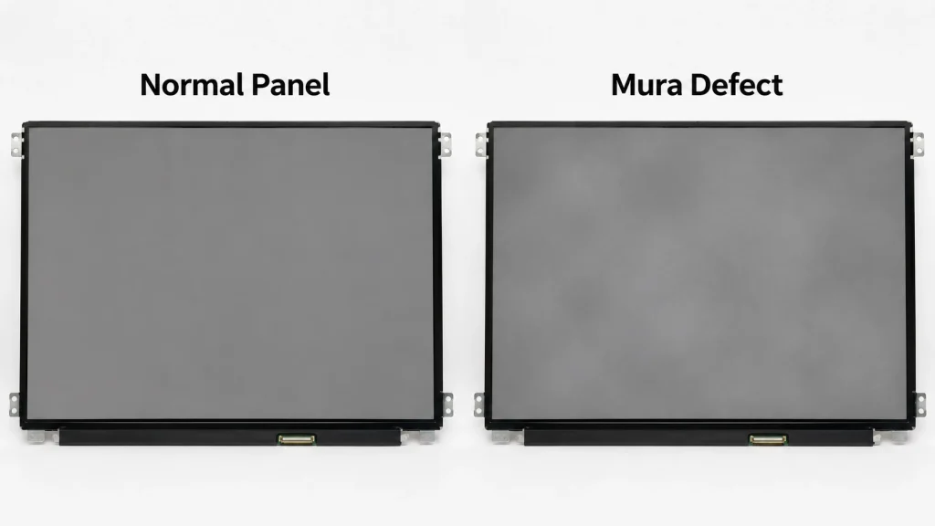
“Mura” (from the Japanese term for unevenness) describes any visible non-uniformity in brightness or color across an otherwise uniform display field. It’s one of the most commonly cited cosmetic defect categories in LCD panel quality control, and unlike most failure modes in this article, mura can be present from day one (a manufacturing defect) or develop progressively over the product’s service life (an aging-related defect).
Categories of mura and their root causes
Pressure mura appears as light or dark patches corresponding to mechanical stress points — often from improper mounting, bezel over-tightening, or impact during transport. The liquid crystal layer is extremely sensitive to cell-gap uniformity; a gap variation of even 0.1–0.2 micrometers across the panel surface is enough to produce visible brightness variation.
Backlight mura results from non-uniform light distribution from the LED backlight array or light guide plate, typically appearing as brighter regions near LED positions and dimmer regions in between. Industrial LCD specifications commonly require luminance uniformity of 80% or higher (minimum luminance divided by maximum luminance across 9 or 13 measurement points per VESA-style test grids) to be considered acceptable for professional use.
Thermal mura develops when temperature gradients across the panel surface cause uneven liquid crystal response — common in displays with localized heat sources nearby (driver boards, power supplies) or in panels exposed to direct, partial sunlight through an enclosure window.
Polarizer mura results from inconsistent stretching or adhesive application during polarizer film lamination, producing subtle color-shifted patches, especially visible at off-axis viewing angles.
Detection and quality thresholds
Industrial panel manufacturers typically test luminance uniformity, chromaticity uniformity (ΔCu, ΔCv variation under 0.01–0.02 across the panel), and visual mura inspection under standardized dark-room viewing conditions before shipment. Panels intended for mission-critical applications — medical imaging, transportation information displays — are held to tighter uniformity tolerances than general commercial displays.
Spot Damage: Localized Failures from Impact, Pressure, and Manufacturing Defects
LCD spot damage refers to a localized, fixed-location defect — typically a dark spot, bright spot, or colored blob — that does not change regardless of displayed content. Unlike mura’s diffuse unevenness, spot damage has a sharp, defined boundary and a fixed pixel location.
Common causes of spot damage
- Physical impact: a point impact on the front glass or cover lens can crack the underlying glass substrate or rupture the cell gap, causing liquid crystal to leak or pool at the impact site — especially common in industrial kiosks subject to vandalism or handheld equipment that gets dropped.
- Pressure-induced cell gap collapse: excessive mounting pressure or a foreign particle trapped between the cover glass and the LCD surface during assembly can create a localized pressure point, producing a colored or dark spot that often appears as a ring pattern under certain viewing angles.
- Manufacturing particle contamination: dust or fiber contamination introduced during cell assembly, before the panel is sealed, can create a permanent dark spot — typically caught during factory optical inspection but occasionally escaping into the field as a latent defect that surfaces after thermal cycling stress.
- Pixel-level defects: individual stuck or dead pixels (a TFT transistor failure at a single pixel location) appear as a single-pixel-sized colored or black dot. Industrial display specifications typically define acceptable defective pixel counts under standards similar to ISO 9241-307, with stricter requirements applied to safety-critical and medical display applications.
Why spot damage matters more in industrial settings
A single dead pixel on a smartphone is a cosmetic annoyance. A single dead pixel obscuring a critical warning indicator on an industrial control panel, a medical monitor, or a transportation information board can have safety implications. This is why industrial-grade panel specifications and optical bonding processes are held to materially tighter defect tolerances than consumer-grade equivalents — and why ruggedized cover lens and impact-resistant bonding (often rated to withstand 50G mechanical shock per MIL-STD-810G testing) are standard requirements for outdoor kiosk and transportation display applications.
Backlight Aging: The Slow Fade That No One Notices Until It’s Too Late
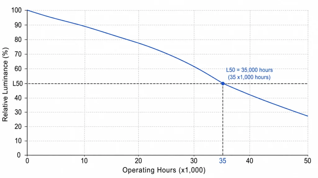
Unlike the other failure modes discussed so far, backlight aging is not a defect — it’s an expected, predictable degradation process inherent to LED technology. The problem is that most system integrators don’t budget for it, leading to ‘failures’ that are really just the backlight reaching end-of-life ahead of schedule due to thermal or electrical stress.
Understanding LED backlight degradation
LED luminous efficiency declines gradually over operating hours due to phosphor degradation, semiconductor junction degradation, and encapsulant yellowing from UV and thermal exposure. The industry-standard metric for this is L70 or L50 lifetime — the number of operating hours until luminance drops to 70% or 50% of initial brightness, respectively.
Typical industrial backlight lifetime figures
- Standard commercial-grade LED backlights: L50 lifetime commonly rated around 30,000–50,000 hours at 25°C ambient.
- Industrial-grade, wide-temperature LED backlights with improved thermal design: L50 lifetime can extend to 50,000–70,000+ hours even at elevated ambient temperatures.
- For every 10°C increase in LED junction temperature above the rated operating point, expected lifetime to a given luminance threshold can drop by roughly 30–50%, following typical Arrhenius-based acceleration models used in LED reliability engineering.
Why backlight aging accelerates in industrial environments
Industrial and outdoor LCD applications frequently demand higher initial brightness — often 1000 nits and above, with some sunlight-readable display modules rated between 1500 and 2500 nits — to remain visible under direct sunlight exposures exceeding 10,000–100,000 lux. Driving LEDs harder to achieve this brightness increases junction temperature and current density, both of which accelerate the degradation curve. Without adequate thermal design, a high-brightness industrial backlight can age through its L70 threshold considerably faster than its rated specification suggests.
Design strategies that extend backlight service life
- Specify LED backlights with margin above the minimum brightness requirement, so that end-of-life luminance still meets the application’s visibility threshold.
- Use automatic brightness control tied to ambient light sensors, reducing LED drive current — and therefore junction temperature — during lower-light conditions.
- Ensure adequate thermal pathways from the LED board to the enclosure, particularly in sealed IP65/IP67-rated outdoor housings where convective cooling is limited.
For industrial deployments requiring both extreme brightness and long service life, panels engineered specifically for sunlight-readable, wide-temperature operation tend to deliver materially better long-term luminance retention. See Kadi Display’s high-brightness LCD displays for outdoor applications for this exact engineering trade-off between sunlight readability and backlight longevity.
Polarizer and Optical Bonding Degradation Under Thermal Cycling

Industrial LCDs deployed outdoors or in vehicles experience repeated thermal cycling — often dozens or hundreds of cycles per year between sub-zero nights and sun-baked afternoons. This cycling places mechanical stress on every bonded interface in the display stack-up, and two specific failure modes dominate: optical bonding delamination and polarizer degradation.
Optical bonding delamination
Optical bonding uses an optically clear adhesive (OCA) to eliminate the air gap between the cover glass and the LCD panel, improving contrast and reducing internal reflection — a near-universal requirement for sunlight-readable displays. However, the OCA layer and the materials it bonds have different coefficients of thermal expansion. Repeated cycling between temperature extremes causes mechanical stress to accumulate at the bonding interface.
Testing data on standard fully-laminated panels has shown delamination areas reaching approximately 2 mm² after 10 thermal cycles between -40°C and 85°C when using standard OCA adhesive around 0.2 mm thick. Wide-temperature engineering solutions — using lower-stress OCA formulations with reduced thickness (around 0.1 mm) and lower modulus (around 0.3 MPa) — have demonstrated delamination areas controlled to roughly 0.5 mm² under the same test conditions, representing a substantial improvement in long-term reliability for displays deployed in extreme climates.
Polarizer film degradation
Standard polarizer films can experience edge lifting, bubbling, or peeling when exposed to sustained heat and UV radiation, since the adhesive layers bonding the polarizer to the glass substrate soften and lose adhesion strength at elevated temperatures. Industrial-grade wide-temperature panels typically specify heat-resistant, UV-stable polarizer materials specifically to prevent this failure mode, maintaining contrast ratios above 1000:1 and viewing angles up to 178° even after years of thermal stress exposure.
FPC and flex cable fatigue
Worth noting alongside optical degradation: the flexible printed circuit (FPC) connecting the LCD panel to its driver board is also subject to thermal-cycling fatigue. Standard FPCs have shown fracture rates of around 10% after 50 cycles between -40°C and 85°C, while industrial-grade FPCs using rolled copper foil (offering roughly 30% improved ductility over standard etched copper) have demonstrated fracture rates closer to 1% under identical test conditions — a meaningful reliability difference for displays expected to survive multi-year deployment in variable climates.
Comparative Summary: Failure Mode Quick Reference
Engineering Takeaways: Specifying Displays That Resist These Failure Modes
When evaluating an industrial LCD module for a new deployment, the failure modes above translate directly into specification checkpoints:
- Operating temperature range: confirm the panel’s rated range (commonly -20°C to 70°C standard, extending to -30°C or -40°C to 85°C for enhanced industrial-grade panels) actually covers your worst-case field environment, including direct sun exposure inside a sealed enclosure.
- Brightness with margin: specify initial luminance well above your minimum readability threshold to account for L50/L70 degradation over the product’s intended service life.
- Bonding and polarizer specification: for outdoor or vehicle-mounted displays, confirm the optical bonding adhesive and polarizer materials are rated for your expected thermal cycling profile, not just static high/low temperature tolerance.
- Mechanical robustness: for kiosk, transportation, or industrial control panel applications, confirm impact resistance ratings (commonly MIL-STD-810G) and IP-rated sealing appropriate to the installation environment.
- FPC and connector quality: in high-cycle-count thermal environments, request data on FPC fatigue life rather than assuming standard commercial-grade flex cable will suffice.
Manufacturers with deep experience in industrial and wide-temperature display engineering typically publish this reliability data directly. Kadi Display’s industrial TFT LCD display module guide outlines the resolution, brightness, interface, and lifecycle factors relevant to this kind of evaluation.
Their wide-temperature TFT display lineup is engineered specifically around the thermal cycling and backlight longevity challenges covered in this article.
Conclusie
Industrial LCD failure modes — image retention, burn-in, mura, spot damage, and backlight aging — rarely appear as sudden, catastrophic failures. They develop gradually, driven by predictable physical and chemical processes: ion migration under sustained static voltage, LED phosphor degradation under thermal and electrical stress, adhesive fatigue under repeated thermal cycling, and manufacturing tolerance stack-up in cell gap and backlight uniformity.
Understanding the underlying mechanism behind each failure mode is what separates reactive troubleshooting from proactive specification. A display selected with appropriate brightness margin, wide-temperature-rated optical bonding, industrial-grade FPC materials, and adequate thermal management for the backlight will avoid the majority of field failures that plague displays repurposed from consumer-grade product lines.
For engineers specifying displays for industrial automation, outdoor signage, transportation, or medical equipment, working with a manufacturer that documents these reliability characteristics — rather than only headline brightness and resolution specs — remains the most effective long-term strategy for minimizing field failures and warranty returns.
For industrial TFT LCD sourcing, wide-temperature display engineering, and custom OEM/ODM display solutions, visit Kadi weergave — a Shenzhen-based manufacturer with over 20 years of experience in high-reliability industrial, medical, and embedded display modules.
Voorgaande
LCD Display Connector Failure Modes: ZIF Lock, FPC Cable, Solder Joint, and Contact Wear
Volgende
Common MIPI DSI Display Problems: Black Screen, Flicker, No Backlight, and Driver Issues
Laat een reactie achter

Laatste Blog & Nieuws
- Industrial LCD EOL: What Happens from Pre-Announcement to Replacement Mass Production?
- Electronic Component Obsolescence Management for Industrial Displays: An OEM Guide
- How to Develop a Production Ready Custom Display Assembly TFT Module Touch Cover Glass FPC Bonding and Mounting
- 15 Pin vs 22 Pin Raspberry Pi DSI Connectors Cable Pinout and Compatibility
- Native MIPI DSI vs LVDS or HDMI Bridge: An OEM Display Architecture Decision Guide

