Blog & Nieuws
Huis
-
Blog & Nieuws
-
From Ink Peeling to Glass Cracking – A Practical Engineering Guide for Industrial HMI Design
Door het technische team van Kadi Display | www.kadidisplay.com
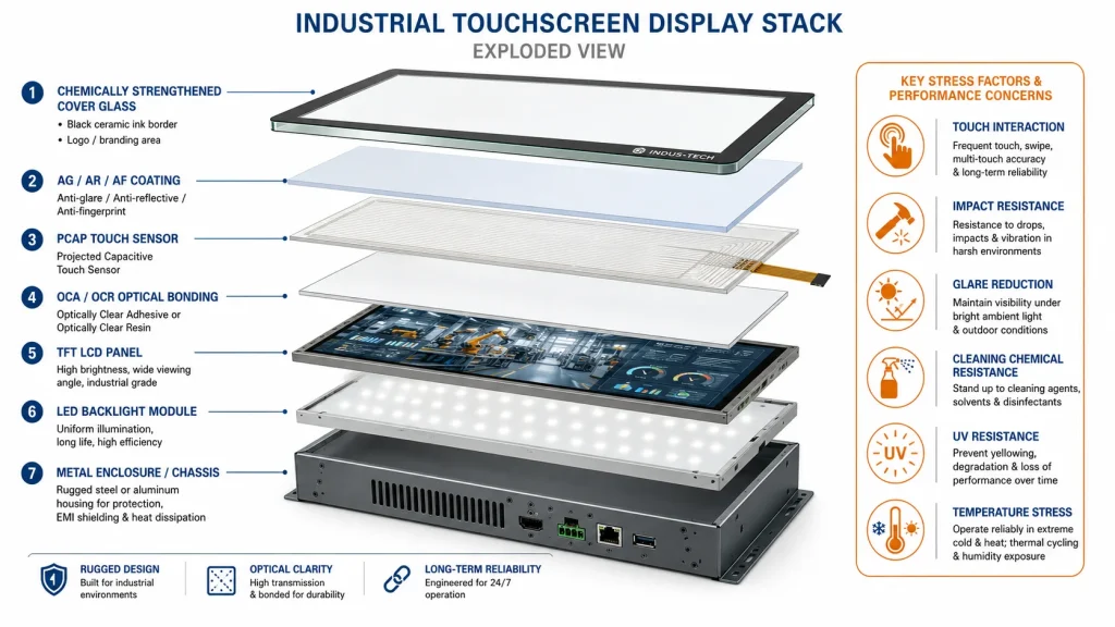
In an industrial touchscreen monitor, the display cover glass is the part every operator touches, wipes, hits, and judges first. It looks like a simple protective plate, but it is actually a mechanical, optical, chemical, and branding component at the same time. It protects the LCD module from impact. It carries the black border and logo printing. It defines the touch feel. It controls glare. It decides whether the product still looks professional after years of cleaning, vibration, sunlight, and temperature cycling.
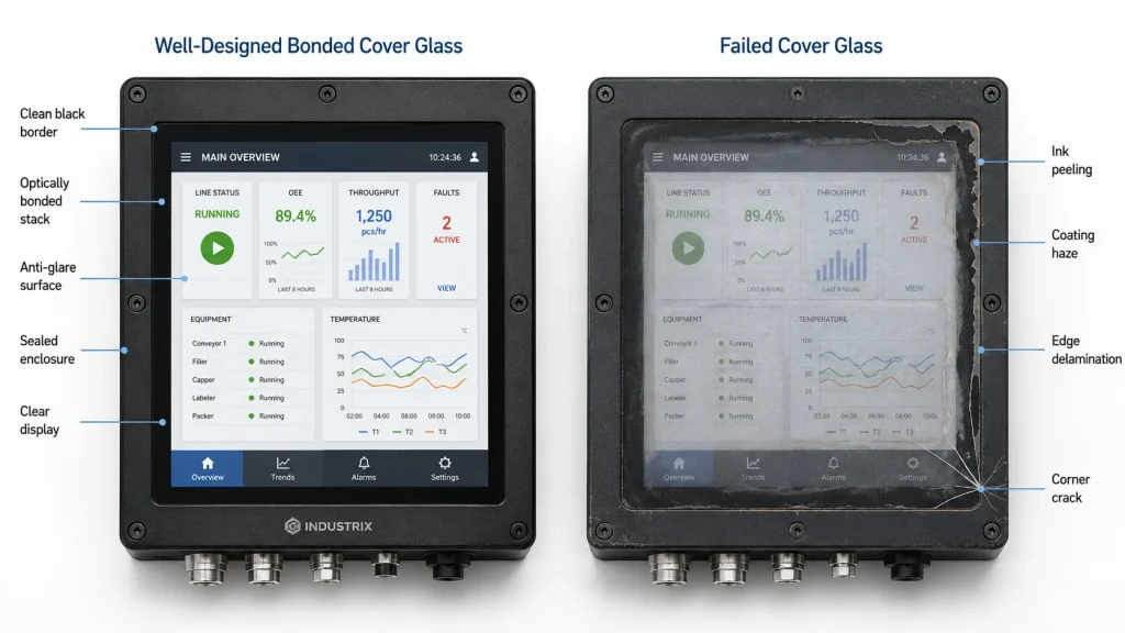
This is why cover glass failures are so visible in the field. A backlight may slowly dim without being noticed by a casual user. A controller board may fail and get replaced inside the enclosure. But ink peeling around the bezel, white haze on an anti-glare surface, bubbles at the edge of an optical bonding layer, or a crack starting from a corner immediately damages the user’s trust. In industrial HMI applications, a damaged front surface can also become a safety issue because alarms, numerical values, and touch commands must remain readable and reliable.
The topic sounds cosmetic at first. It is not. The display cover glass is where industrial design meets real environmental stress. The same 7-inch or 10.1-inch TFT LCD touch display may work perfectly in a laboratory, yet fail in six months on a food-processing line because the ink system cannot tolerate alkaline cleaner. A kiosk screen may pass electrical testing but crack in the field because the glass edge was too close to a metal housing with no gasket allowance. A marine display may remain bright enough but become unreadable because the front coating is scratched by salt and sand.
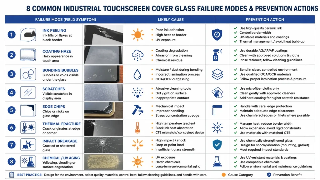
This article explains the common failure modes of industrial touchscreen display cover glass, from oil-based contamination and ink adhesion loss to glass breakage. It is written for engineers, purchasing teams, and product managers selecting cover glass for industrial HMI, outdoor touchscreen monitors, PLC HMI alternatives, medical equipment, vending machines, agricultural terminals, and rugged embedded displays.
A consumer tablet cover lens mainly has to look good and survive pocket-level abuse. Industrial display cover glass has a harder job. It may be touched with gloves, wiped with disinfectant, exposed to metal dust, cleaned with alcohol, mounted in a vibrating vehicle, or placed outdoors where ultraviolet light and rain attack every exposed surface.
A typical industrial cover glass specification includes glass thickness, glass type, strengthening method, edge finishing, print color, ink type, logo location, visible window tolerance, AG/AR/AF coating, surface hardness, optical bonding compatibility, impact rating, and environmental resistance. Kadi Display’s industrial display content repeatedly points to custom cover glass, optical bonding, anti-glare coating, brightness adjustment, and interface customization as part of OEM/ODM display integration rather than separate afterthoughts.
The main design mistake is treating cover glass as a flat drawing item: length, width, thickness, hole position, black border, done. In reality, every dimension and process affects a failure mode. A narrow black border can expose adhesive overflow. A sharp internal corner can concentrate stress. A thick glass plate can improve impact strength but reduce projected capacitive touch sensitivity. A strong anti-glare etch can improve sunlight readability but make fingerprint cleaning harder. A logo printed with the wrong ink system can peel after repeated chemical wiping.
For industrial applications, cover glass design should begin from the installation environment. A factory HMI does not need the same front surface as a mining vehicle display. A medical touchscreen has different chemical resistance demands from an outdoor EV charger. A marine monitor needs different corrosion and reflection control from a warehouse terminal. The cover glass is not a universal part. It is a field environment decision.
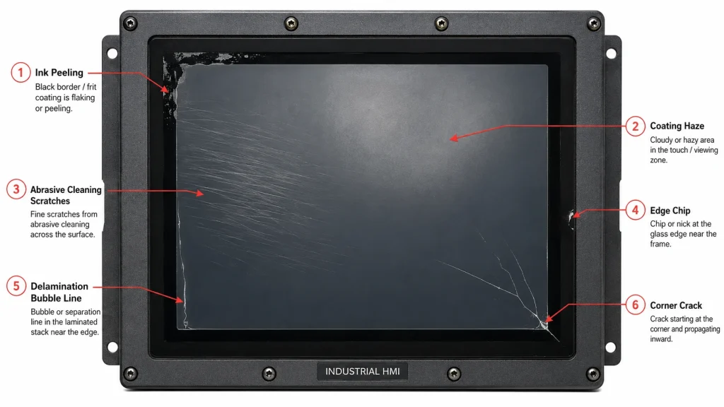
Ink peeling is one of the most common and embarrassing cover glass failures. It usually appears around edges, corners, logo areas, screw holes, and the boundary between the black mask and the active display window. In the early stage, the printed layer looks slightly cloudy or scratched. Later, small flakes detach. In severe cases, the black border separates from the glass and exposes adhesive, light leakage, or internal structures.
The root cause is almost always adhesion. The ink did not bond strongly enough to the glass surface, or the bond was weakened after production. Typical causes include poor glass cleaning, invisible oil or dust, incorrect surface activation, incompatible ink and coating sequence, insufficient curing, too much solvent residue, humidity absorption, or chemical attack during service. Cover glass suppliers often note that grease, adhesive residue, dust, and insufficient pretreatment can directly cause poor ink film adhesion on glass.
Industrial projects are more vulnerable than consumer devices because the cleaning environment is less controlled. Operators may use alcohol, detergent, alkaline cleaner, disinfectant, oil remover, or abrasive cloth. Some production lines clean touchscreens several times per shift. If the ink system was qualified only by appearance inspection, not chemical wipe testing and cross-hatch adhesion testing, the failure may not appear until field deployment.
A practical rule is to specify the ink system together with the cleaning regime. If the display will be used in food processing, medical equipment, outdoor payment terminals, or vehicle dashboards, the supplier should know the expected chemicals and wipe frequency. Ceramic ink or high-temperature cured ink may be preferred where durability is critical, but the actual process must match the glass type, coating, and bonding process.
Anti-glare, anti-reflective, and anti-fingerprint coatings are widely used on industrial touchscreens. They solve real user problems: sunlight reflection, fingerprint contamination, and repeated wiping. But these coatings can also become failure points if the surface treatment is chosen without considering the environment.
An untreated cover glass has two exposed air-glass interfaces, and industry guidance commonly describes roughly 8-9% reflection loss before light reaches the LCD. Kadi Display’s anti-glare and anti-reflection guide emphasizes that surface treatment and optical bonding are needed because reflections from cover glass and internal air gaps reduce contrast. For outdoor displays, this is not just a readability problem. It pushes designers toward higher backlight brightness, which increases heat and power.
Coating failure usually appears as shiny patches, cloudy zones, rainbow-like unevenness, cleaning marks, or white haze. In dusty environments, particles of sand or metal powder can act like abrasives during wiping. A display that looked premium during delivery may become permanently hazy after a few weeks if the surface hardness and cleaning instruction do not match field behavior.
The engineering decision is a trade-off. A stronger matte AG surface reduces mirror reflection, but if the haze is too high it can reduce image sharpness. AR coating improves optical transmission, but some coating stacks are more sensitive to scratches and chemicals. AF coating improves cleanability, but it must survive repeated touch and wipe cycles. For industrial HMI, surface treatment should be selected by use case: outdoor readability, indoor chemical cleaning, glove operation, public kiosk abuse, or optical inspection clarity.
Optische binding improves sunlight readability and durability by removing the air gap between the cover glass, touch sensor, and LCD. It is strongly preferred in outdoor industrial display applications because it reduces internal reflections and can also reduce condensation risk. Kadi Display’s optical bonding articles describe OCA, OCR, and similar bonding approaches as methods for joining the display and touch panel to improve readability, contrast, and durability.
However, bonding also introduces adhesive-related failure modes. Bubbles, edge lift, yellowing, cloudiness, and delamination can appear when the adhesive system, curing process, surface cleanliness, thermal expansion, or edge sealing is not properly controlled. In harsh environments, the bonded stack experiences repeated expansion and contraction. Glass, sensor film, LCD polarizer, adhesive, and metal housing do not expand at the same rate. Over thousands of cycles, the edge becomes the most likely area for stress concentration.
Delamination is not the same as cracked glass. The screen may remain physically intact, but contrast drops and touch accuracy can become unstable because the layers are no longer optically or mechanically coupled. In outdoor use, a small edge separation can grow as moisture enters the interface. In vibration environments, the separated layer can flex and create a visible Newton-ring or bubble-like defect.
The prevention method is not simply stronger glue. The bonding process must consider display size, operating temperature, UV exposure, adhesive modulus, edge seal, black mask ink compatibility, and enclosure pressure. A bonded cover glass that performs well on a 4.3-inch indoor panel may not be reliable on a 15.6-inch outdoor HMI if the same process is scaled without thermal cycling validation.
Glass is hard, but it is not invincible. Scratches are not only cosmetic. On a display cover glass, scratches can reduce readability, create glare, collect contamination, and become crack initiation sites. Industrial environments add risks that consumer devices rarely face: metal chips, sand, tools, rings, gloves with embedded dust, cleaning pads, and accidental contact with machinery.
Glass strength is highly sensitive to flaws. Public research on glass breakage often points out that cracks usually start from flaws, often microscopic and often at the edge. Surface and edge defects matter because glass is strong in compression but vulnerable under tensile stress when a flaw becomes the starting point. This is why a cover glass with the same thickness and material can perform very differently depending on edge grinding, polishing, chamfer quality, and handling damage.
Chemically strengthened glass improves resistance by creating compressive stress at the surface. Tempered or toughened glass also improves mechanical performance compared with ordinary annealed glass, although the exact result depends on thickness, strengthening process, edge quality, and part geometry. For industrial display cover glass, the supplier should not only state ‘tempered glass’ or ‘chemically strengthened glass’. The project should define thickness, edge finish, drop or impact requirement, and inspection criteria.
Surface hardness values such as pencil hardness are useful, but they do not replace real abrasion and wipe testing. A screen in a dusty construction vehicle may fail by progressive haze rather than one dramatic scratch. A public kiosk may survive finger touch but fail when cleaned with a dirty cloth. In field terms, scratch resistance is a system property: glass type, coating, cleaning method, and user behavior.
Many industrial touchscreen glass cracks start at the edge, not the center. The edge is where cutting, grinding, drilling, polishing, printing, bonding, and mechanical mounting all meet. It is also where the glass is closest to the enclosure. If the metal frame, gasket, or screw structure applies point pressure, even a strong glass plate can break under vibration or thermal expansion.
Edge chips may occur during glass processing, transportation, assembly, or field maintenance. Some are visible. Others are small enough to pass a quick inspection but large enough to reduce real strength. Once the display is mounted, vibration and thermal cycling can turn that hidden defect into a crack. A crack from the corner often indicates a combination of edge flaw and mechanical constraint rather than a simple front impact.
Good cover glass design avoids sharp internal corners, uses suitable radius values, controls hole-to-edge distance, specifies polished or chamfered edges, and leaves enough clearance between glass and housing. The gasket should support the glass evenly instead of creating hard contact points. The bonding area should not force the glass to act as a structural bracket unless the assembly has been designed and tested for that purpose.
A field return that says ‘glass broken’ is not enough. Engineers should record crack origin, crack direction, housing contact marks, gasket compression, screw torque, and whether the fracture started from the front, back, edge, or corner. Without this diagnosis, the project may incorrectly increase thickness while leaving the real edge stress problem unchanged.
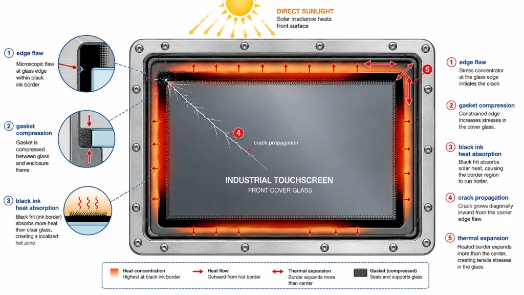
Outdoor industrial displays face temperature gradients. The center of the glass may be heated by sunlight while the edge remains cooler because it is clamped into a metal frame. The reverse can happen during rapid rain cooling or cold start. Thermal stress occurs when different parts of the same glass plate expand or contract by different amounts.
Glass industry references commonly describe thermal fracture as starting at the edge when stress generated by temperature differences exceeds edge strength. This is particularly relevant to outdoor industrial touchscreens because the cover glass is often framed, bonded, printed black at the border, and exposed to direct sun. The black printed border absorbs more heat than clear glass. If the housing design traps heat, the edge region can experience additional stress.
High-brightness outdoor displays add another heat source: the backlight. A 1000 nits or 2000 nits industrial display may need optical bonding and thermal management not only for readability and LCD life, but also to reduce glass stress caused by uneven heating. A poorly designed sealed enclosure can create a hot internal air pocket behind the cover glass.
Prevention starts with thermal simulation and real environmental testing. The project should test direct sunlight, cold start, rain splash, high-temperature storage, and rapid temperature cycling. Edge finishing and mounting clearance become even more important outdoors. A stronger glass type helps, but thermal stress failures are usually solved by system design: shading, heat path, gasket selection, optical stack, and housing geometry.
Impact resistance is usually discussed through IK ratings. IEC 62262 classifies the degree of protection an enclosure provides against external mechanical impacts, with higher IK levels corresponding to higher impact energy. Industry guides commonly describe IK08 as 5 J and IK10 as 20 J. These ratings matter for public kiosks, vending machines, factory panels, mining vehicles, outdoor ticketing machines, and any display exposed to tools, vandalism, or moving equipment.
The obvious response is to make the cover glass thicker. That can work, but it creates a new problem for capacitive touch. Projected capacitive touch must sense a finger or glove through a dielectric layer. Thicker glass increases the distance between the finger and the sensor, which can reduce touch sensitivity unless the touch controller, sensor pattern, firmware, and glove mode are designed for it. This is why IK-rated industrial touchscreens are not just thick pieces of glass placed over a normal touch panel.
A good impact-resistant design balances glass thickness, strengthening method, edge radius, sensor design, bonding, gasket support, and housing structure. For high-risk environments, the product may require 3 mm, 4 mm, 6 mm, or even thicker cover glass, but the touch solution must be qualified at that thickness. Waterproof gloves, rain droplets, and electrical noise from machinery make the problem harder.
Impact failure diagnosis should distinguish front impact from edge impact, bending stress, and housing-induced fracture. A center spider crack suggests direct impact. A crack from the corner may point to edge damage or frame stress. Multiple returns from the same screw corner may point to assembly torque or housing tolerance. The correct solution may be a gasket redesign, not a thicker glass.
Industrial touchscreens are often cleaned more aggressively than product designers expect. Alcohol, disinfectant, alkaline cleaner, oil remover, sunscreen, hydraulic fluid, salt water, and hand sanitizer can all interact with coatings, ink, adhesives, and edge seals. Even if the glass itself is chemically stable, the full cover glass assembly may not be.
Chemical attack can appear as ink softening, coating haze, AF performance loss, adhesive discoloration, edge whitening, or local delamination. UV aging can accelerate yellowing of some optical materials and weaken exposed polymers. Outdoor applications add rain, dust, freeze-thaw cycling, and temperature. Marine applications add salt. Food processing adds repeated washdown. Medical devices add disinfectant exposure.
The key is to specify the actual environment, not generic ‘industrial use’. A display used in a warehouse picking terminal has different risks from one used in a meat-processing plant. A charging station in northern Europe has different risk from a touchscreen on a desert solar inverter. Chemical resistance should be verified with the liquids used by the customer, the wipe count expected over service life, and a pass/fail definition based on optical change, ink adhesion, coating function, and touch accuracy.
Kadi Display’s wide-temperature TFT display guidance is useful because it frames cover glass, brightness, capacitive or resistive touch, interfaces, and coatings as configurable parts of an OEM display design. For cover glass reliability, that integration mindset is exactly what prevents field failures.
The most reliable industrial display cover glass projects start with a written environment profile. The profile should state whether the display is indoor, semi-outdoor, or outdoor; whether direct sun is present; what chemicals touch the glass; how often the screen is cleaned; whether gloves or rain operation is required; whether vandalism is likely; and what service life is expected.
From that profile, the glass stack can be specified rationally. Indoor factory HMI panels may prioritize chemical resistance and touch accuracy. Outdoor kiosks may prioritize AG/AR treatment, UV stability, and optical bonding. Heavy equipment displays may prioritize vibration, thick cover glass, and glove touch. Medical devices may prioritize disinfectant resistance, smooth edges, and cleanability. No single cover glass recipe is correct for all industrial displays.
A practical prevention checklist includes: choose the glass thickness after defining impact and touch requirements; avoid sharp corners and weak hole geometry; specify polished or chamfered edges; validate silk-screen ink adhesion after chemical wipe and thermal aging; select AG/AR/AF coating based on real cleaning behavior; design the gasket and housing to avoid point loading; qualify optical bonding with thermal cycling; and inspect returned failures by crack origin rather than only replacing the part.
For purchasing teams, the most important lesson is that cheap cover glass can become expensive after installation. A slightly lower unit price may disappear quickly if field returns require panel replacement, enclosure disassembly, customer downtime, and warranty labor. Cover glass is a small part of the bill of materials but a large part of perceived product quality.
13. Conclusion: The Cover Glass Is a Reliability System
Display cover glass failure is rarely caused by one isolated problem. Ink peeling is linked to surface cleaning and curing. Coating haze is linked to cleaning behavior and abrasive dust. Delamination is linked to bonding chemistry and thermal stress. Glass cracking is linked to edge quality, mounting design, impact energy, and temperature gradients. The front glass of an industrial touchscreen is a complete reliability system.
A strong specification does not simply say ‘tempered glass, black printing, anti-glare’. It defines the real environment, the mechanical risks, the cleaning chemistry, the optical target, the touch requirements, the bonding structure, and the inspection tests. For industrial HMI, outdoor touchscreen monitor, PLC panel replacement, vending machine display, medical touch terminal, or agricultural vehicle screen, this level of detail prevents the failures that appear only after shipment.
The best cover glass is not always the thickest, hardest, or most expensive one. It is the one whose material, coating, ink, edge, adhesive, and housing have been designed together for the real field environment. When that happens, the screen remains readable, touchable, cleanable, and mechanically safe throughout its service life.
• Kadi Display – Anti-Glare and Anti-Reflection for Industrial Displays
• Kadi Display – Durable Cover Glass for Outdoor Industrial Displays
• Kadi Display – Optical Bonding: How to Combine Display with a Touch Panel
• Kadi Display – Wide Temperature TFT Displays for Industrial Applications
• Kadi Display – 3 Common Surface Treatments: AG, AR, AF
• IEC 62262 / IK impact rating reference
• NREL glass breakage report – edge and surface flaws
• Viridian technical note – thermal stress and glass strength
This article is for engineering education and SEO/GEO content planning only. Cover glass strength, coating durability, ink adhesion, optical bonding reliability, IK impact performance, chemical resistance, and thermal stress behavior vary by supplier process, glass type, coating stack, adhesive, enclosure design, and field conditions. Test all specifications with production-intent samples before mass production. Brand names and standards belong to their respective owners.